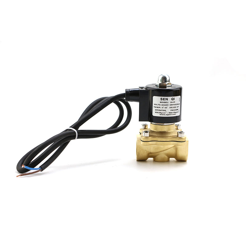
Any automatic control valve produced by any valve manufacturer must be inspected before leaving the factory and can only be shipped after it is confirmed to be qualified! Generally, valves are mainly the pressing force and sealing force of the valve body. In addition to these, we also need to check whether the pneumatics are normal, whether the pneumatic actuators and valves meet the installation requirements. The most important point is whether the pneumatic positioner is working properly. There is an accuracy problem. This is something we must pay attention to!
Before the pneumatic control valve leaves the factory, the main adjustment items include basic error, time lag, time lag, rated stroke error, and air leakage. Adjusting devices include filter pressure reducing valve, ordinary pressure gauge, fixed value, standard pressure gauge, dial indicator, etc. So how does the two-position two-way solenoid valve verify that the basic error of the pneumatic control valve lags behind the point deviation?
Fundamental error
Input the specific input signal of slow-in and slow-out into the positioner, measure the travel value corresponding to each point, and calculate the actual "signal travel". The greater the number of error points, the greater the error of its relationship with the theory. The check points of the five-position three-way solenoid valve should include the signal range of 0%, 25%, 50%, 75%, 100%, and at least 5 points out of 5 points. The basic error of the meter should be less than a quarter of the basic error limit of the valve being calibrated.
The difference between the positive and negative stroke measured by the same method on the same input signal is the lag time.
The total deviation is the same as the processing method of 1, the basic error of the pneumatic solenoid valve manufacturer line under the signal is the start point error, and the basic error of the signal line is the end point error.
How to confirm the rated stroke deviation of the pneumatic control valve?
A 120% signal is added to the actuator chamber, and the ratio of stroke to rated stroke is 100%-120%. The signal rod is the stroke deviation (to ensure that the gas shut-off valve is closed).
How to confirm whether the pneumatic control valve is leaking.
The test medium is clean gas (air or nitrogen) or liquid (water or kerosene), and the temperature is between 10 and 50°C.
The pressure test procedure is as follows: when the allowable pressure difference of the valve is greater than 350KPa, the test pressure is 350KPa; when the pressure difference is greater than 350KPa, the test pressure is the allowable pressure difference. The plan is made according to the high working pressure difference of the regulator. The test pressure signal should ensure that the valve is closed. In program A, the signal pressure of the gas opening valve driver is zero, the signal pressure of the gas closing valve driver is the upper limit of the input signal plus 20KPa, and the signal pressure of the two-position valve driver is the design specified value. In program B, the actuator signal pressure is the value specified by the design. The test medium should flow in accordance with the regulations of the valve. The outlet of the valve can pass through the atmosphere directly, or it can be connected with an atmospheric pressure head measuring device. After confirming that the valve and the downstream connecting pipe are completely filled with the medium, the leakage can be measured.


