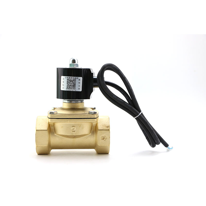
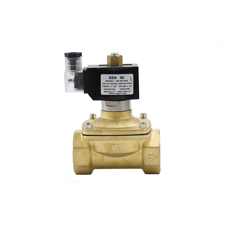
At present, the pneumatic fluorine control valve produced by the valve manufacturer adopts high pressure injection molding technology at the contact part with the medium, and is lined with corrosion-resistant and aging-resistant polyperfluoroethylene propylene (F46 for short), and adopts four-way solenoid valve PTFE bellows. It is sealed, so it is widely used in industrial process control systems such as chemical industry, petroleum, metallurgy, medicine, electric power, etc. It can be used for strong corrosive media such as acid and alkali, as well as toxic and volatile gas and liquid media.
The regulator has become an indispensable fluid control device in the above-mentioned various fields. Promoting the continuous development of domestic valve manufacturing enterprises' technology, how to improve product performance, reliability and reduce costs has also become the primary task of valve manufacturing enterprises.
The role of the regulator in various use environments is to dredge and intercept the medium. Therefore, the solenoid valve water valve controls the flow rate during the use of the valve. It is important to control the flow rate before selecting and using the regulator. Test to see if it meets our requirements.
Flow rate is an important process parameter and technical index of valves, regulating valves and other industrial valves. It refers to maintaining the pipeline pressure constant, or the volume flow through a valve, or the flow rate under a test condition and within a unit time. Volume, that is, the flow capacity of the valve. If the regulator is fully opened, the pressure difference ΔP between the front and rear ends of the valve is 100KPa, and the concentration of the first conductive magnetic valve fluid is 1gf/cm3 (ie normal temperature water), then the flow rate flowing through the regulator per hour in the regulator is expressed in m3/ h or t/h.
Increase the inlet pressure of the pressure reducing device. For any lower rate, for accurate pressure reading, when the pressure reaches the desired set pressure. Observe and record the set pressure and other required or related characteristic values of the equipment. Continue to increase the inlet pressure of the device until the device reaches and maintain the discharge state. At the same time, observe the action of the device and record the discharge pressure and opening height.
Then gradually reduce the input pressure until the device is closed. At the same time, observe the action of the device and record the return pressure. During the displacement test, the set pressure, discharge pressure and return pressure are all determined and stable values. The inlet pressure of the booster device reaches and remains at the rated discharge pressure until the flow measuring instrument shows a steady state. The pressure drop check of the regulator is to check whether the pressure drop at both ends of the regulator changes, whether there is bubble or flashing phenomenon, how the flow rate changes, whether the flow rate conforms to the original design, etc. during the simulation debugging of the fresh water and the full stroke operation of the regulator.
The regulating valve should be kept in a stable discharge state, and the data should be read and recorded according to the same procedure at a predetermined time interval, including the inlet pressure of the pressure release device, the discharge temperature of the calorimeter at the inlet of the pressure release device, the loading height of the pressure release device, and the inlet of the flow meter. Static pressure, pressure difference of flood gauge, discharge temperature of flow meter, etc.


